1. Architectural Components & Configurations
This section breaks down the physical architecture of a Stirling engine. Understanding these control volumes and kinematic linkages is essential before analyzing the thermodynamics. The engine consists of coupled thermal spaces, a fluid shuttling mechanism, and energy extraction/storage components.
Hot Chamber (VE)
The high-temperature reservoir expansion space. External heat (Qin) expands the gas here, performing positive boundary work.
Cold Chamber (VC)
The low-temperature sink compression space. Heat rejection (Qout) occurs here, minimizing required work input during compression.
The Displacer
Found in Beta & Gamma types. Shuttles fluid between hot/cold chambers with negligible pressure differential (ΔP ≈ 0).
Power Piston
Seals the fluid and acts as the mechanical interface. Driven by instantaneous uniform pressure P(t). Net work: W = ∮ P dV
Flywheel
Kinematic energy storage. Acts as a mechanical low-pass filter, storing kinetic energy (Ek = ½Iω²) to drive compression phases.
Configurations
- Alpha: Two independent power pistons.
- Beta: Displacer & power piston in same cylinder.
- Gamma: Displacer & power piston in separate cylinders.
2. Ideal Thermodynamic Cycle (P-V Diagram)
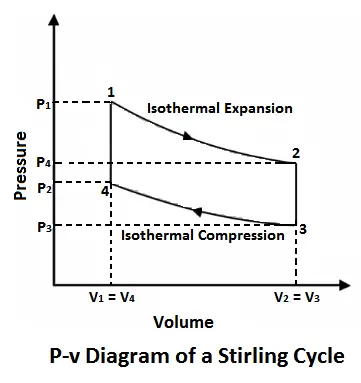
This section maps the four idealized phases of the Stirling cycle onto a Pressure-Volume (P-V) diagram. Click through the phases below to see the corresponding mathematical formulation, physical action, and how it translates to the thermodynamic state change on the chart.
System Efficiency
Assuming 100% regenerator effectiveness, matches Carnot limit:
3. Advanced Kinematics: Schmidt Isothermal Analysis
In reality, piston motion is harmonic (sinusoidal), causing isochoric and isothermal phases to overlap. The Schmidt Analysis models these continuous volume changes based on the crank angle (θ). Use the slider below to adjust the phase angle (α) between the expansion and compression spaces to see its effect on the total system volume.
VE(θ) = (VSE/2) * (1 - cosθ)
VC(θ) = (VSC/2) * (1 - cos(θ - α))
Total Mass (m) is constant, applying ideal gas law across all internal volumes enables solving for instantaneous pressure P(θ), generating an elliptical, real-world P-V diagram.
4. Regenerator & Working Fluid Thermophysics
Engine power density and efficiency rely heavily on the thermal capacitor (Regenerator) and the thermophysical properties of the working fluid. This section compares standard fluid choices.
The Regenerator Matrix
Absorbs heat during isochoric cooling and returns it during heating. Thermal effectiveness (ε) dictates efficiency. If ε < 1, external heat must bridge the gap, degrading efficiency. Increasing density improves ε but increases aerodynamic flow friction (ΔPdrop) and dead volume (VR).
Air
Convenient, safe. Low thermal conductivity (k), high molar mass. Limits engine to low speeds due to severe flow losses.
Hydrogen (H2)
Thermodynamically ideal. Lowest viscosity (μ), highest thermal conductivity. High diffusivity causes embrittlement/leakage, high flammability risks.
Helium (He)
Industrial standard. Inert noble gas. High specific heat ratio (γ ≈ 1.66) gives substantial pressure swings for high power density without H2 risks.
Relative Comparison of Key Thermophysical Properties